 Gadgetorium
 Cylon Goggles
Created: 2026-08-13
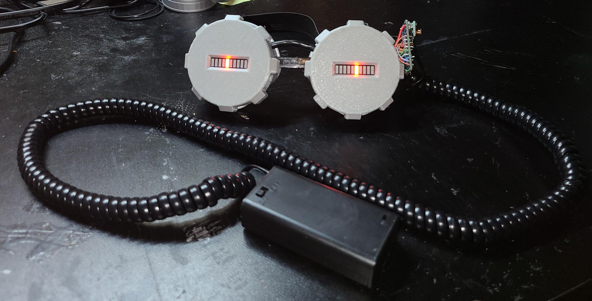
Custom costume goggles with red LED bars that animate.
 Original
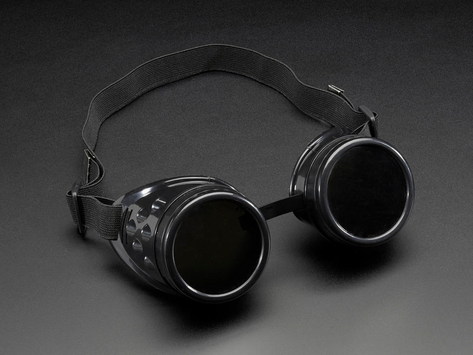
Image from
adafruit.com
My sister gifted me plastic goggles like these on a whim. I don't have a photo of them unmodified, but they are nearly identical to the ones from Adafruit. The lenses were not tinted, and there was some brass colored paint splattered on the housings. I sanded off that original paint and spray-painted them silver.
Design
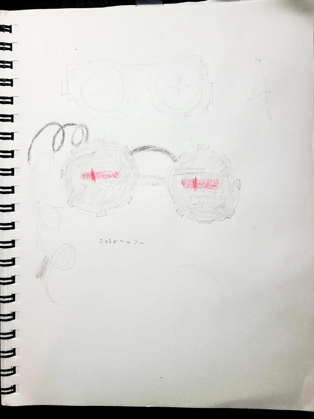
I considered using LED rings like some of the examples on Adafruit. I also thought of using small discrete LEDs or LED filaments with gaps around them so that they could be seen through. However, I had some LED bargraphs from a project I never made. Since the goggles wouldn't fit over my glasses, I wasn't concerned with being able to see through them.
Construction
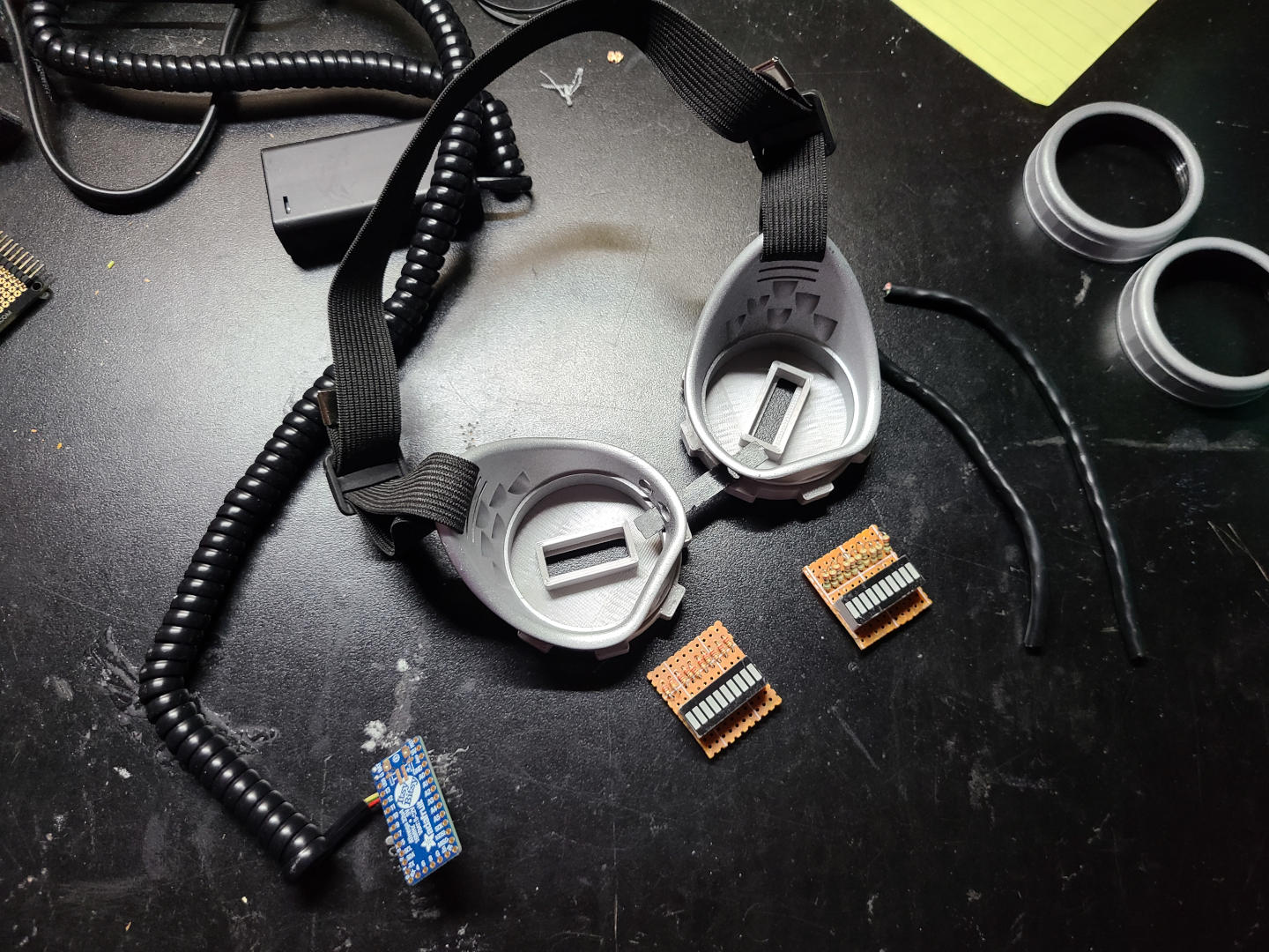
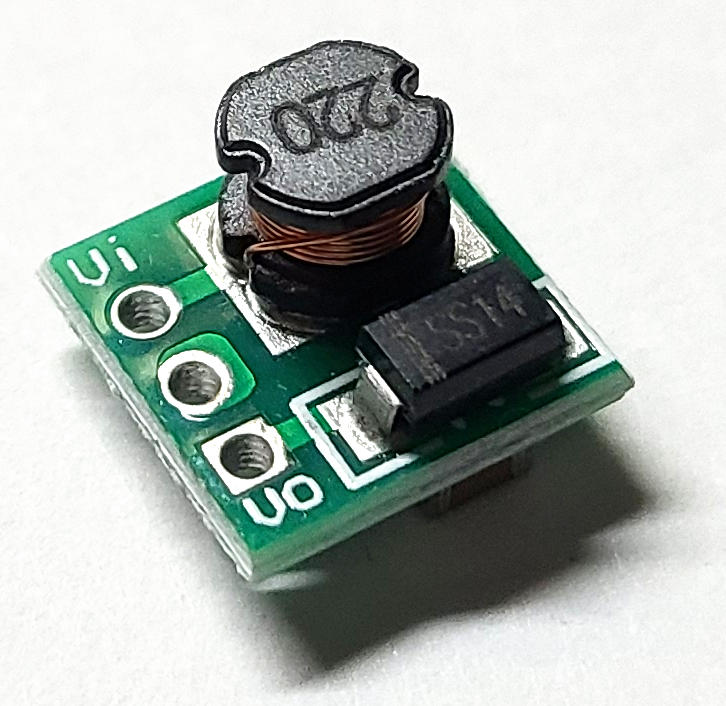
First, I attached a boost regulator to an Adafruit ItsyBitsy (outputting to its "battery" pin), and connected it to a two AA battery box with some coiled phone cord. I had used the same circuits on the shelf robot and had spares. I wasn't sure if two AAs would provide enough power, but it was able to power up the microcontroller. (Later I found that it actually lasted pretty long running the whole circuit!)
The 3D-printed parts ended up being very straightforward. The lens holders on the goggles screw on, so I made parts with threads that could screw on in their place. The LED modules friction fit into place.
I agonized over the LED wiring for a while, wondering if I should use some kind of interface board or multiplexing to reduce the wiring. Eventually, I decided to commit to using only parts I already had, and wire all the LEDs directly. The ATMega32U4 has just enough pins and power to run everything directly. There are power limits per certain groups of pins. To be safe, I picked pins so that no more than 7 LEDs would be on any group. In practice, there are never that many LEDs on, but it provided some safety in development.
I soldered each LED module to a piece of perfboard with current-limiting resistors on each cathode. The anodes are all bridged together. One LED on one module died, possibly due to some testing I was doing to figure out how the resistors affected brightness. There was a bad connection on the breadboard, and the LED was very dim even with very low value resistors. I tried it out of the board with a coin-cell, and it was much brighter. It still worked once I moved the breadboard connection, but maybe that segment was marginal after being exposed to high current and low voltage, and the heat of soldering broke it all the way? I had a spare module, but I was out of 220 ohm resistors and had to order more.
I drilled holes and ran two pieces of CAT-5e between the lenses, one tucked behind the bridge piece. I ended up removing most of the pairs from the 2nd one (keeping one pair) and slipping a thicker wire into it for the common anode connection. The connections for the wearer's left module are some thin ribbon cable run through one of the vents on the side of the goggles. The modified CAT-5e connects the LEDs on the right.
In the sketch, I had the cable coming out of the wearer's right side, but I moved it to the left so that it could go in a shirt/coat pocket. I wanted to wear the goggles to AnimeFest. (If you're one of the people there that I handed a card to, hi!) I ran out of time to cover the wiring. So I cable-tied the battery wire to another vent, and left the rest as is. The 20 stiff CAT-5e wires keep the circuit board from moving.
I made a couple alternate animations in the firmware, which cycle with each power-up. There's one where the Cylon pattern extends all the way across, and another where the LEDS step from the bridge outward.

© 2026 Kyle Delaney | Site Map

 (mp4)
(mp4)